Constructor/Reference/Single3DViewForm
From TDN
Contents
|
|
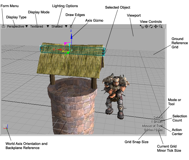
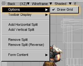
[edit] Single 3D View Form IntroductionThe Single 3D View Form is the user's view into the scene they're currently editing. By moving, rotating and zooming a virtual camera the user may view all objects in the scene or choose to focus on a single item. The Form also supports a number of different drawing methods that you'd expect in a typical 3D modeling application. This section describes the various parts that make up the Single 3D View Form and how the user operates them. [edit] Interface TourBelow is a description of the various controls and informational text that makes up the Single 3D View Form. [edit] Form MenuThe Single 3D View Form menu has a couple of options that are saved with the layout. The first menu item toggles the display of the reference grid.
[edit] Display Type PopupThe Display Type popup is used to set where the camera views the scene and its projection method. The popup's selection is saved with the layout. The following choices are available: |
| Display Type | Description |
|---|---|
| Top | Orthographic view of the XY plane looking down the negative Z-axis. [numpad 1] |
| Bottom | Orthographic view of the XY plane looking down the positive Z-axis. [numpad 2] |
| Front | Orthographic view of the XZ plane looking down the negative Y-axis. [numpad 3] |
| Back | Orthographic view of the XZ plane looking down the positive Y-axis. [numpad 4] |
| Left | Orthographic view of the YZ plane looking down the positive X-axis. [numpad 5] |
| Right | Orthographic view of the YZ plane looking down the negative X-axis. [numpad 6] |
| Perspective | Perspective view of the scene with camera which may be rotated. [numpad 7] |
| Texture | A special view of the UV coordinates for all selected brush faces. [numpad 8] |
|
[edit] Display Mode PopupThe Display Mode popup determines how the scene is drawn and its selection is saved with the layout. The following choices are available: |
| Display Mode | Description |
|---|---|
| Wireframe | All objects draw as only wire frame edges. |
| Solid | All objects are drawn as solids without texturing and are affected by the sunlight. |
| Textured | Objects are drawn as solid and textured and are affected by the sunlight. |
| By Brush | All brush-based geometry is given a different random color per brush. Static meshes are drawn in the Solid mode. All objects are affected by the sunlight. |
| By Face | All brush-based geometry is given a different random color per brush face. Static meshes are drawn in the Solid mode. All objects are affected by the sunlight. |
| Export | This special display mode only draws brush-based geometry that has been generated by using the Scene->Generate Export Preview menu. When combined with the Shaded lighting option each brush face is given a different random color. When combined with the None lighting option the export preview is drawn textured but without shading. |
|
[edit] Lighting Options PopupThe Lighting Options popup determines how the in-scene lighting and optional sunlight affects object rendering. The popup's selection is saved with the layout. The following choices are available: |
| Lighting Option | Description |
|---|---|
| None | All objects are drawn without any lighting other than 100% ambient white light. Reference shapes are drawn with OpenGL direct lighting as produced by the virtual sun. |
| Shaded | All objects are drawn with OpenGL direct lighting as produced by the virtual sun. Light entities do not affect the rendering. |
| Mapped | When combined with the Scene->Relight Current or Scene->Relight All menu items all objects are lit and shadowed using lightmaps. The virtual sun is included if the Preview With Sunlight option is set under the Lighting Profiles window opened with Scene->Manage Lighting Profiles... menu item. Reference shapes are drawn with OpenGL lighting from entities only. If a light entity is moved then its lightmap contribution is approximated and added back into the scene. |
| Dynamic | Draws objects with a lightmap approximation minus shadow casting or the virtual sun. Moving light entities affects the rendering. |
|
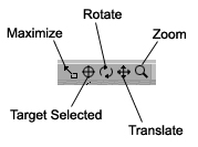
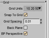
[edit] Draw Edges ButtonWhen this toggle button is enabled all brushes and static meshes draw in the current display mode with a wire frame overlay highlighting their polygonal edges. The color of the edges may be modified with the Outline Color preference found under the System->Preferences... menu. [edit] View ControlsThe View Controls allow manipulation of the Form and viewport and will display differently depending on the current display type. Orthographic displays do not have the Rotate button. The Maximize button is used to toggle the Form from its current size to its maximum size covering all other Single 3D View Forms given the current layout. Due to the dynamic nature of Constructor's layout the maximize operation does a 'flood fill' of sorts to determine how large the Form may be maximized. The Maximize button's keyboard shortcut, numpad 0, is applied to the Single 3D View Form currently under the mouse pointer. The Target Selected button will make the viewport always center on the currently selected object. While something is targeted the viewport's display may not be moved although the rotation and zoom operations are still operational. When nothing is selected the viewport may be manipulated as usual. The Target Selected button's keyboard shortcut, numpad decimal, is applied to the Single 3D View Form currently under the mouse pointer. The last three controls are drag buttons that duplicate the functionality described in the Manipulating the Viewport section below. The user holds down the left mouse button on the Rotate, Translate or Zoom controls and drags the mouse. This will rotate, translate or zoom the viewport as appropriate. [edit] The GridThe grid is the ground plane reference in Constructor, or more specifically it represents the XY plane at Z=0. It is drawn with major and minor tick marks whose spacing is dependant on the distance of the view's camera to the target. The current minor tick mark spacing (the light gray lines) is always shown in the bottom right corner of the viewport. In the example Single 3D View Form image at the top of this page this value is '0.5m' or half a meter. Other than the individual viewport grid drawing, all grid parameters are modified on the Preferences Form under the Grid section. This is under the Prefs tab in the default layout.
[edit] Grid UnitsAs the camera zooms in and out from the target the grid resizes itself to remain useful. The steps at which this resizing occurs is determined by this popup. Valid values are: |
| Grid Units | Description |
|---|---|
| 10 | The grid resizes in factors of 10, as in 10m, 1m, 0.1m, etc. |
| 10 20 | The grid resizes in factors of 10 and 20, as in 10m, 2m, 1m, 0.2m, 0.1m, etc. |
| 10 25 | The grid resizes in factors of 10 and 25, as in 10m, 2.5m, 1m, 0.25m, 0.1m, etc. |
| 10 50 | The grid resizes in factors of 10 and 50, as in 10m, 5m, 1m, 0.5m, 0.1m, etc. |
| 10 20 50 | The grid resizes in factors of 10, 20 and 50, as in 10m, 5m, 2m, 1m, 0.5m, 0.2m, 0.1m, etc. |
| 10 25 50 | The grid resizes in factors of 10, 25, and 50, as in 10m, 5m, 2.5m, 1m, 0.5m, 0.25m, 0.1m, etc. |
|
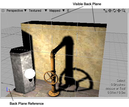
[edit] Snap To Grid and Grid SpacingThese two settings go together. When Snap To Grid is activated all Axis Gizmo and tool mouse operations in the viewport will snap to the nearest Grid Spacing unit. In the example image above the snapping occurs every 0.01m or 1cm. [edit] Back Plane and BP PerspectiveThe Back Plane is another reference plane that is used only within a Perspective display type viewport. Its purpose is to provide a 2D build reference when using tools so that most geometry creation may be performed while working in the Perspective mode. To see the Back Plane in action, activate the Back Plane (to draw the plane) and BP Perspective (to have it affect tool operations) preferences.
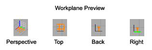
The position of the Back Plane is also determined by the location of the Perspective viewport's camera as it 'snaps' to each major tick mark on the ground reference grid. With the Back Plane active -- whether it is drawn or not -- it acts as the construction plane that intersects all mouse operations. It's like working with the orthographic views but within the Perspective display. When the Back Plane is disabled using the BP Prespective preference, then the ground reference plane becomes the Back Plane of sorts and all mouse operations within a Perspective view intersect with it. The best way to understand the Back Plane is to use it. Try using the Build Cube tool a few times in the Perspective view while rotating the camera around and changing the Back Planes' orientation. [edit] Mode or Tool IndicatorThis line of text at the bottom right of the viewport simply indicates if the user is in selection mode, written as Select, or is using a tool. When a tool is active its name is displayed here. [edit] Selection CountThis line of text at the bottom right of the viewport provides both a count of the number of selected objects as well as an indication of the current selection mode. [edit] Current Action CenterThe current Action Center determines how the user interacts with selected geometry using the tools. For example, where the center of rotation or scale will be. This is set either from the Tools Form's Modify tab or using the Edit->Action Center menu. The current Action Center is displayed over the viewport as a reminder of its setting. [edit] World Axis Orientation GizmoThis gizmo is located in the lower left of the viewport and displays three different pieces of information. The first is that it shows the orientation of the world's axis as viewed through the viewport's camera. This is displayed as red, green and blue lines representing the X, Y and Z axis. The second piece of information is a representation of the current Back Plane, if any.
Finally this gizmo indicates that a custom Workplane has been activated. How it indicates this depends upon the viewport's current display mode.
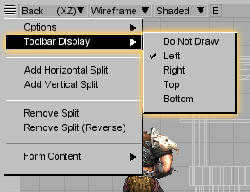
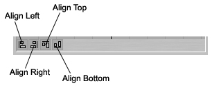
[edit] ToolbarThe Toolbar may be activated and placed around the Form using the Form Menu. It currently contains four tools which are really meant to operate on the orthographic views although they are functional in the Perspective view.
[edit] Manipulating the ViewportUsing the mouse is the primary method of manipulating the viewport's camera. Whenever the camera's view is changed a small axis appears within the viewport. This provides a frame of reference for a number of the camera's movement options. There are a few options for the viewport's camera which may be found under the Prefs tab of the standard layout's Properties Form, the Preferences Form itself, or by using the System->Preferences menu. The camera may operate in two modes: Orbit and Free Roaming. The current mode is toggled by clicking on the Free Cam check box or pressing the C keyboard shortcut. Orbit always rotates and zooms the camera in reference to the target and may never go past the target. When you move the camera you're actually moving the target and dragging the camera along. Free Roaming makes the camera act like in a FPS game where rotation is centered on the camera and zooming moves the camera and target together. The Move Speed preference determines how fast the camera may roam the scene. Depending on the camera's mode mouse buttons and keyboard shortcuts behave differently. A summary is provided below. |
Orbit Mode
| Button or Key | Operation |
|---|---|
| Right Button | Perspective view: Rotate about target Orthographic view: Move camera and target left, right, up and down |
| CTRL+Right Button | Orthographic view: Contract or expand the field of view |
| Middle Button | Move camera and target left, right, up and down |
| CTRL+Middle Button | Move camera and target left, right, in and out |
| Scroll Wheel | Perspective View: Move camera towards and away from target, but never past Orthographic view: Contract or expand the field of view |
| CTRL+Scroll Wheel | Zoom slower With ALT zoom even slower |
| SHIFT+Scroll Wheel | Zoom faster With ALT zoom even faster |
| W+Right Button S+Right Button | Perspective view: Move camera and target forwards and back |
| S+Right Button D+Right Button | Perspective view: Move camera and target left and right |
Free Roam Mode
| Button or Key | Operation |
|---|---|
| Right Button | Perspective view: Rotate about camera bringing the target along Orthographic view: Move camera and target left, right, up and down |
| CTRL+Right Button | Orthographic view: Contract or expand the field of view |
| Middle Button | Move camera and target left, right, up and down |
| CTRL+Middle Button | Move camera and target left, right, in and out |
| Scroll Wheel | Perspective View: Move camera and target forwards and back Orthographic view: Contract or expand the field of view |
| CTRL+Scroll Wheel | Zoom slower With ALT zoom even slower |
| SHIFT+Scroll Wheel | Zoom faster With ALT zoom even faster |
| W+Right Button S+Right Button | Perspective view: Move camera and target forwards and back |
| S+Right Button D+Right Button | Perspective view: Move camera and target left and right |
|
|
| Key | Operation |
|---|---|
| F | Fit all selected objects so that they are within the viewport. If nothing is selected then all objects are brought into view. |
| CTRL+F | Fit all objects into view. |
| G | Center the point under the mouse pointer within the viewport. |
| . | Zoom the camera in one step. |
| , | Zoom the camera out one step. |
|
[edit] The Axis GizmoInformation on the Axis Gizmo may be found on its own page. [edit] Using Tool HandlesInformation on using standard tool handles may be found on its own page.
|


